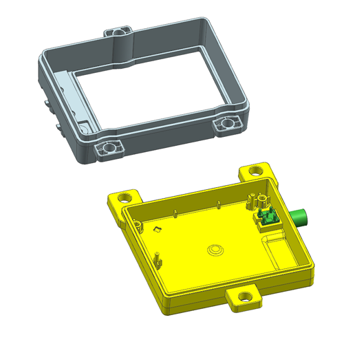
Prototype Injection Molds
Fast T0/T1 tooling for validation, pilot runs, and bridge production.
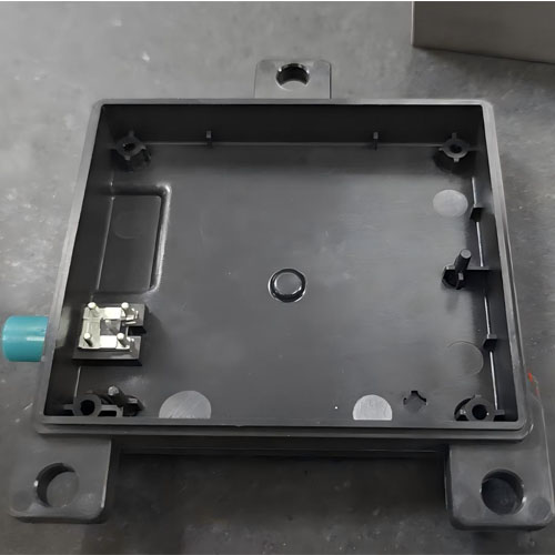
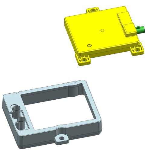
Prototype molds are built for speed without sacrificing the engineering fundamentals (filling, venting, cooling, ejection, and serviceability). Use this option when you need real injection-molded samples to validate fit, function, and assembly—before committing to long-life production tooling.
- Typical use cases: T0/T1 sampling, design validation, assembly fit checks, pilot runs, bridge tooling
- 24h response: feasibility notes + DFM risk flags within 24 hours
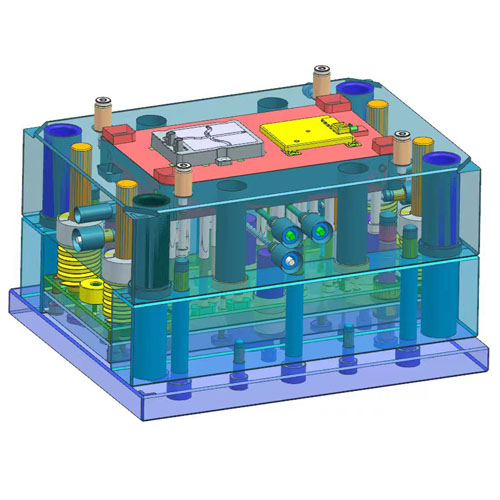
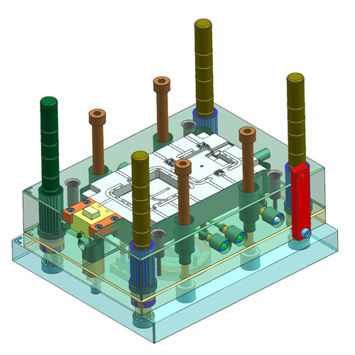
What Is a Prototype Mold (Engineering Definition)
A prototype mold is optimized for speed-to-sample and controlled iteration:
- Fast build + fast iteration (modular inserts on risk areas)
- Predictable sampling results (stable gating/venting/ejection)
- Clear learning outcomes (what to change on the part or the tool, and why)
The goal is not “the cheapest mold.”
The goal is the fastest reliable learning cycle to de-risk your production tool.
What You Need to Send for a Fast Quote
- 3D CAD (STEP/IGES) + 2D drawing if available
- Material/resin + additives (GF, FR, UV, etc.)
- Appearance requirement (gloss/matte/texture, cosmetic side)
- CTQ dimensions & tolerance targets
- Expected volume (prototype qty, pilot run, annual projection)
- Target timeline (T0/T1 timing)
- Special requirements (insert molding, 2K, sealing, marking limits)
Key Cost Drivers
- Geometry risk (thin wall, shutoffs, undercuts, cosmetic faces)
- Cavity count & layout (single/multi/family)
- Runner & gating constraints (weld-line control, gate type)
- Surface finish requirement
- Iteration plan (need modular inserts or not)
Typical Lead Time & Process
- Tooling concept + quotation package: 1–3 days after data completion
- Tool build: typically 15–25 days (complexity-dependent)
- T0/T1 sampling: immediately after assembly readiness
Common Prototype Failure Modes & Fix Strategy
1) Short Shot / Burn Marks (Gas Traps)
Cause: insufficient venting, trapped air pockets
Fix: proactive venting layout, gate direction optimization, localized vent features
2) Flash at Shutoffs / Inserts
Cause: weak shutoff design, fit drift
Fix: tighten critical insert fit, strengthen shutoff design, define wear areas early
3) Ejection Marks / Part Damage
Cause: insufficient draft, poor ejection layout
Fix: ejection concept review, part-protection logic, draft recommendations
4) Warpage / Dimensional Drift
Cause: unbalanced cooling, residual stress
Fix: cooling balance improvements, DFM geometry notes, controlled process window
Parameters (Typical Tool Material Options)
| | |
|---|
| | Best when geometry is stable and the cosmetic target is moderate |
| | Cost-effective for conventional materials and short runs |
| Demanding prototypes/bridge tooling | Better stability for longer pilot runs |
| Cosmetic-focused prototypes | Good surface potential and consistency |
| High polish/corrosion resistance | Ideal for PC/PMMA or high-gloss requirements |
Start a Free 24h Feasibility & DFM Review
Send your 2D/3D files (STEP) or product photos with key dimensions. We’ll respond within 24 hours.
Not sure which one is right for you?
- Need stable low-volume production before final tooling is completed? → Bridge Tooling